wpo - a reflective spectroscopic slit & its application
The criteria for the construction of a traditional spectroscopic slit are listed and a novel alternative is described together with its potential advantages. The application of the new slit mechanism in a compact single-lens spectrograph and spectrohelioscope is then described, enlarging on a brief outline given before the BAA Ordinary Meeting on 1980 January 30.
Introduction: The spectroscopic slit provides a line source
of light for analysis by the grating or prism; for astronomical purposes
it is typically from 20 micron to 1000 micron (1 mm) in width. The larger
slit size is usually reserved for the high-resolution stellar spectrograph
via coude optics7. The smaller slit may be more applicable to
solar work where plenty of light is available or where the instrument is
scaled down in size as often in amateur work. In recent years a slit produced
via a gap in an aluminised glass plate has found some favour, but the traditional
mechanical slit with metal jaws continues to hold sway. The basic constraints
of this device could be summarised as follows :
 Traditional
slit
Traditional
slit
( i ) The edge of each jaw face must be plane, straight and free
from serrations, dust and potential corrosion to avoid horizontal lines
streaking the spectra.
( ii ) The jaws must be set parallel and square to each other
and correctly aligned to the imaging optics and grating.
( iii ) The jaws must be fixed or adjustable to a specific separation.
( iv ) The bevelled edge of the jaws (to be set on the collimator
side) must not give ghost images, by reflection via the slit
of the source under examination. Figure
1 shows the basic arrangement.
Construction of a traditional slit mechanism: Item ( i ) above is probably the most difficult for the amateur constructor to satisfy. The problems are aggravated by the narrow slit sizes his instrumentation demands, particularly as any defects may be a sizeable percentage of the slit width. However with care satisfactory results can be obtained. Details for the construction of a precision slit mechanism can be found in Amateur Telescope Making2. A modest starting point can be blades from a disposable razor araldited to a 35 mm plastic slide holder.
It is, however, important in dissecting the razor, which must be new and unused, that the blade edges do not come into contact with any surface, including each other, particularly whilst they are brought together to form the slit. A low-power microscope is therefore almost essential for checking that the blade edges are free from defects, for aligning the two blades to form the slit and for making a scale by which to judge the slit. The latter can be arranged by inserting a fine metric steel scale into the microscope carriage and with both eyes open, comparing the enlarged image as apparently projected onto a card beside the microscope. The known width is then subdivided on the card down to 10 micron intervals if necessary. Tweezers or adhesive tape can be useful in handling the fragile blades and some controlled reduction of slit width is possible if the blades are temporally taped together and gentle heat applied. A number of slits of differing pre-set widths can be fabricated in this way for a few pence each although the work is necessarily exacting. It was during such an onerous occasion in 1978 April that an alternative to this device suggested itself - namely a sewing needle! Within minutes the spectroscopic optics had been rearranged and the substitution made. It worked like a charm.
The reflective slit: The needle can be regarded as a negative reflective cylinder imaging within its surface its entire surroundings in a horizontal plane, whilst acting as a plane mirror in the vertical axis. If for example a beam of sunlight is played onto this relatively large surface a fine horizontal spray of light is sent through virtually 360o with an effective width in any particular direction of only a fraction of the cylinder diameter. The ball bearing as a reflective sphere is the analogy for a point source. Subsequent correspondence with the Royal Greenwich Observatory3 indicated that the device was known in the laboratory to produce a line source but that its application in the spectroscope was probably novel. The absence until 1979 May of a quality grating precluded a proper evaluation, but a list of points prepared at the time of the initial experiments appear partially vindicated by current trials ( i-ix). The points are listed below.
Reflective slit
( i ) Ready-made examples of reflective slits
abound in home/workshop/ laboratory.
( ii ) The quality of the reflective surface in the
horizontal plane may be relaxed partially as only a small percentage
on this axis is used.
( iii ) As a virtual (negative) image of the slit is produced,
and this is below the cylinder surface, dust and surface defects
are out-of-focus.
( iv ) The formula for the effective slit width is :
cos (d/4f) q
/
2 where d = diameter of reflective cylinder
f = f/ratio of OG
q = angle between OG and collimator
(v) Matching of OG and collimator f/ratios is
unnecessary, as full illumination of the grating is inevitable, barring
collimator vignetting.
(vi ) An infinite number of spectroscopes or slit guidescopes
may be served by a single reflective slit in an arc about the
cylinder, assuming the image on the cylinder is not a finite point.
If it were a slit would not be necessary.
(vii ) Alignment comprises spraying a sample of light
from the reflective slit onto the collimator lens so that the width of
the beam is at right-angles to the grating ruling.
(viii ) If the reflective slit is spun e.g. if the polished shaft
of a mini motor is used then clean spectra result. Add a vertical oscillation
for very clean spectra. [Note: both these techniques successfully
tested prior to BAAJ publication]
(ix) The system can fold a spectroscope in half for
space saving.
(x) The slit can be rocked about the vertical
axis to broaden stellar spectra.
(xi) Comparison spectra can be recorded simultaneously
with primary spectra by locating the source directly above or below the
OG.
(xii) Fine radial velocities can be measured directly by
feeding the comparison source onto the slit at an angle to the OG centre
line (viewed using an image intensifier).
 The above apply
to reflective cylinders which have zero dispersion in the vertical
axis and all the items may not be exclusive to reflective slits. Modifications
could be made to the vertical profile via barrel or coneshaped reflectors.
An 'S' profile could provide both negative or positive dispersion to the
vertical axis as required, and a cylinder of elliptical cross-section a
variety of slit widths dependent upon the radius of the surface presented
to the image.
The above apply
to reflective cylinders which have zero dispersion in the vertical
axis and all the items may not be exclusive to reflective slits. Modifications
could be made to the vertical profile via barrel or coneshaped reflectors.
An 'S' profile could provide both negative or positive dispersion to the
vertical axis as required, and a cylinder of elliptical cross-section a
variety of slit widths dependent upon the radius of the surface presented
to the image.
Figure 2 shows the basic arrangement.
Characteristics of the reflective slit: The reflective slit possesses some markedly different optical properties from those of the traditional slit and it may be useful to amplify some of these points. Needles from 0.5 mm to 2 mm diameter and OG optics from f/4 to f/25 will provide an effective range of slit widths from 5 micron through to 125 micron quite sufficient for many applications. However, reflective slits need not be confined to this range of cylinder size. For example coude optics at f/60 will require a 240 mm diameter cylinder (or part reflective surface of 120 mm radius) for a 1 mm (1000 micron) effective slit width. A chromed cylinder of 25 mm diameter can be useful to demonstrate the principles of the reflective slit utilising a slide projector beam or sunlight as a light source. In the latter respect five or six prominent Fraunhofer lines can be detected in a darkened room simply by intercepting sunlight reflected off a chrome tube with a piece of acetate replica grating at the eye. A quality grating will improve this resolution at least 10-fold, even to the naked eye.
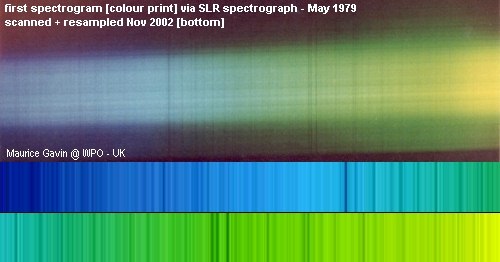
At the opposite extreme it is quite feasible to produce a reflective slit of less than a micron in width by using an aluminised fibre-optic rod, perhaps for application to far U V spectroscopy. Alternatively two needles in juxtaposition will provide a cascade of reducing slit widths via multiple reflections, which may be selected by masking. A usable slit measuring 5 mm x 20 micron represents only 0.1% of the surface area of a typical sewing needle 36 mm long x 1 mm diameter, i.e.14% of the length and 0.6% of the circumference. Any surface blemish is therefore more critical along the length rather than around the circumference for selecting a given slit from the 1000 on offer in the example given! Sample reflective slits as described and resultant spectrograms were shown at the BAA Exhibition Meeting in 1979 May.
Optics and derivation of formula: It is difficult for the unaided eye to appreciate the fineness of the spectroscopic slit and why its mechanical precision should approach optical perfection. A low-power microscope will make this more apparent and help in the selection of a needle that is, for example, as free as possible from scoring defects, which will cause horizontal streaking of spectra. Whilst undertaking such an examination using a desk lamp for illumination, it can be noted that the lamp (representing the illuminated OG) is not sharply in focus on the needle surface but on a point about half the radius of the needle below the surface, forming a 'virtual' or negative image.
 This is precisely
analogous to the Newtonian telescope where the prime focus image
is at half the mirror radius. The apparent reduction of slit-width with
increasing angles of incidence of the lamp (OG), and differential focusing
of each slit edge in these circumstances, will also be evident. The effect
of the collimator f/ratio on the slit width appears negligible when it
is slower than f/2. The above investigation forms the basis of the
formula [cos (d/4f) q/2].
This is precisely
analogous to the Newtonian telescope where the prime focus image
is at half the mirror radius. The apparent reduction of slit-width with
increasing angles of incidence of the lamp (OG), and differential focusing
of each slit edge in these circumstances, will also be evident. The effect
of the collimator f/ratio on the slit width appears negligible when it
is slower than f/2. The above investigation forms the basis of the
formula [cos (d/4f) q/2].
Effect of f/ratios: In the traditional slit-spectrograph
the final f/ratios of OG and collimator should match for a point (stellar)
source. With an extended source, like the Sun in a spectrohelioscope, the
collimator must be of faster f/ratio than the OG in order to accommodate
the overall widening of the beam emerging from the slit, and resulting
from the scan (unless fixed slits and Anderson prisms are used).
Some vignetting of the grating or the image is inevitable therefore.
With a reflective slit such matching is unnecessary for either application
as the needle will illuminate the collimator (and everything else through
nearly a 360o arc) even if moved during a scan. As a needle
slit comprises an infinite number of adjacent reflective surfaces, an adjoining
area will always satisfy the collimator as its neighbour moves on so that
the rays linking OG and collimator become effectively elastic.
Vignetting in these terms is nil and gross mismatching of f/ratios will
only effect image brightness with potential resolution remaining unchanged.
See figure 3.
 Slit types:
In the selection of suitable reflective slits for amateur application,
spectrograms using a spinning slit (the polished shaft of a mini-motor)
show a 50% reduction in horizontal streaking compared with the stationary
mode. Better results can at present be obtained using a selected
(stationary) needle. The most promising area for research may be
drawn glass rod which has been aluminised or with other selected metalizing
for broad-band work.
Slit types:
In the selection of suitable reflective slits for amateur application,
spectrograms using a spinning slit (the polished shaft of a mini-motor)
show a 50% reduction in horizontal streaking compared with the stationary
mode. Better results can at present be obtained using a selected
(stationary) needle. The most promising area for research may be
drawn glass rod which has been aluminised or with other selected metalizing
for broad-band work.
Folded instruments: One of the advantages of the reflective slit is its ability to fold the whole instrument in half for space saving so that the OG and collimator may be placed next to each other. If the grating is arranged to send the light back through the collimator a separate camera or viewing telescope can be dispensed with in the mode of autocollimator. Clearly if a single lens is large enough it can do all three tasks with a reflective slit and camera body at the common focal plane! Such an arrangement is shown in Figure 4.
A single-lens reflective spectrograph: This instrument is based upon a Wray astrographic camera equatorially mounted to produce high-resolution solar spectrograms with only minor modifications. It provides an effective test-bed for some of the unusual characteristics of the reflective slit.
The lens and baffling: The lens is of telephoto construction with 900 mm effective focal length designed to cover 230 mm x 230 mm film at the full aperture of f/4. With such a large field the lens is tolerant of off-axis applications. The clear aperture of the front element is 230 mm, sufficient to accommodate the grating adjacent to its outer surface in the upper-spectrographic section with a 75 mm aperture, B, in the field stop immediately below to serve as OG. A horizontal baffle J separates the two sections and both autocollimator and OG work at f/12. No vignetting of the grating occurs as the field stops F/G to the autocollimator section are rectangular, matching the grating shape. Stop E masks the brilliant image of the needle slit from being reflected off the lens elements into the eyepiece, which has an extended hood H blocking all light except from the grating area. The precise size and position of the field stops, grating and needle slit were arrived at after much experimentation to ensure that the minimum of scattered light within the lens is transferred from the OG section to the grating and, ultimately, to the eyepiece. This might have been impractical if the complex lens design (five-elements in four-groups) had not been fully coated on all eight glass-to-air surfaces.
 The Manning
grating: The grating has a ruled area of 56 mm x 75 mm with 600
lines/mm, and is contained in a cell that can be tilted by a threaded rod
to bring any selected spectral region into view. The lens cone which
supports the grating in front of the lens has provision for fine adjustment
of the grating alignment relative to the eyepiece.
The Manning
grating: The grating has a ruled area of 56 mm x 75 mm with 600
lines/mm, and is contained in a cell that can be tilted by a threaded rod
to bring any selected spectral region into view. The lens cone which
supports the grating in front of the lens has provision for fine adjustment
of the grating alignment relative to the eyepiece.
The camera and slit: At the rear of the instrument a rack-mount supports a 35 mm SLR camera body, or an eyepiece, with a needle typically of 1 mm diameter suspended vertically below the camera at the common focal plane. Focusing is particularly sensitive with a push-pull action to the film plane and reflective slit respectively. The separation of about 50 mm between the centre-lines of the camera and the needle is equalised about the optical axis of the lens. Minor adjustments of the needle alignment are necessary to ensure illumination of the grating. The effective slit width is about 20 micron. It is important that only light from the OG section falls on the needle to form the reflective slit and that all adjacent surfaces are matt black, otherwise ghost slits may be acquired from any bright surface in the plane of the slit and be reflected back onto the grating.
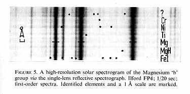
The instrument in use: Visually the instrument is a delight
to use, clearly resolving, for example, the solar lines FeI (5168.908A)
from FeII (5169.050A) in green light. This is a difference of 0.142A
against a theoretical limit of 0.115A set by the instrument for first-order
spectra. An estimated 10,000 solar lines are probably accessible visually
and half this number photographically for the lowest order of spectra.
The visual prime focus image of the solar spectrum extends some 230 mm.
Even so the resolution is so high as to be generally finer than the grain
structure of regular film emulsions. Thus to glean the fullest information
in the spectra extenders (Barlows) of x3 or x9 are used to enlarge
the primary image.
(see Figure 5).
Photography: Regular fine-grain films like Ilford FP4 appear satisfactory from near UV (3800A) to about Ha (6563A) with Kodak 2475 or SO-115 extending the response into the far red. Some progressive shift of focus is evident whilst traversing the visible spectrum, showing up the residual chromatic aberrations of the Wray lens. Focusing when using Kodak HS Infra-red film is therefore a matter of trial and error. If the highest resolution is required, the second to fifth-order spectra are used with acetate colour filters external to the OG to isolate the overlapping orders.
Photometry: If the camera is replaced by a simple photoelectric photometer10 and a chart recorder, line profiles from 5000A to 10,000A (near IR) may be recorded for immediate readout by scanning the spectra.
Spectrohelioscope conversion: If suitable, a high-resolution
spectrograph can be converted into a spectrohelioscope to view the Sun's
disk in a selected wavelength, usually Ha. The
chosen wavelength is precisely isolated at the spectrographic focal plane
by a second slit (S2) which, moving in synchronisation with the first slit
(S1), scans and builds up an image rendered visible by persistence of vision.
The scanning device can take various forms4,5.
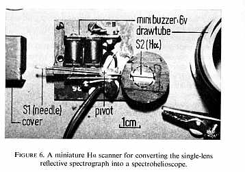 Ha
scanner : In the conversion of the single-lens reflective spectrograph,
the camera and reflective slit are replaced by a 28g scanner that is small
enough to fit into the rack-mounted drawtube (figure
6). The two slits, placed 50 mm apart, are carried at opposite
ends of an arm attached direct to a small 6 v buzzer mechanism oscillating
30 cps through an angle of 3o. S1 is a needle projecting
below the drawtube into the prime focus image of the Sun produced by the
OG section, and set parallel to S2 which is a traditional slit with jaws
located centrally in the drawtube. Each slit is about 20 micron wide. Using
a x 25 eyepiece of 36 mm focal length behind S2, a 4'arc wide strip
of the Sun can be scanned at any instant. The image is direct and
unreversed, like the naked eye Sun. The grating is adjusted to bring the
general Ha region adjacent to the stationary
slit, S2, and then the drawtube (carrying the whole scanning mechanism)
is slightly rotated until the Ha line aligns
with the notches at each end of S2 and the buzzer is switched on for viewing.
The grating has a blaze efficiency approaching 85% in redlight8
of first-order spectra, making it eminently suitable for Ha.
Before the above can become a reality, however, there are several vital
points to consider.
Ha
scanner : In the conversion of the single-lens reflective spectrograph,
the camera and reflective slit are replaced by a 28g scanner that is small
enough to fit into the rack-mounted drawtube (figure
6). The two slits, placed 50 mm apart, are carried at opposite
ends of an arm attached direct to a small 6 v buzzer mechanism oscillating
30 cps through an angle of 3o. S1 is a needle projecting
below the drawtube into the prime focus image of the Sun produced by the
OG section, and set parallel to S2 which is a traditional slit with jaws
located centrally in the drawtube. Each slit is about 20 micron wide. Using
a x 25 eyepiece of 36 mm focal length behind S2, a 4'arc wide strip
of the Sun can be scanned at any instant. The image is direct and
unreversed, like the naked eye Sun. The grating is adjusted to bring the
general Ha region adjacent to the stationary
slit, S2, and then the drawtube (carrying the whole scanning mechanism)
is slightly rotated until the Ha line aligns
with the notches at each end of S2 and the buzzer is switched on for viewing.
The grating has a blaze efficiency approaching 85% in redlight8
of first-order spectra, making it eminently suitable for Ha.
Before the above can become a reality, however, there are several vital
points to consider.
Instrumental constraints: Firstly, the spectrohelioscope imposes on the needle a particularly stringent requirement not necessary in the spectrographic mode i.e. the long axis of the needle acts as an optical flat to image the Sun. Failure to do so would curtail the project. It came as both relief and delight to find that an ordinary sewing needle could satisfy these requirements and produce a sharp image of the Sun in monochromatic light when magnified at least x 30, a point that could only be verified in the scanning mode.
Secondly, whereas it is acceptable to have the Sun's image defocused on the slit (S1) in the spectrograph - one is analysing light within the instrument - this would be clearly unacceptable for viewing the Sun's disk. The rack-mount carrying S1 and S2 has a common focusing movement and can accommodate only two of the three functions of the Wray lens as OG, collimator and viewing scope at any one moment. For this reason, S2 at the end of the optical train is arranged to have an additional movement along the axis to fine tune the whole system to a sharp focus.
Finally the spectrohelioscope is expected to view the Sun's disk from within what appears to be a black absorption line, whereas the spectrograph is quite content to record it as just that. Therefore light impinging on or leaving S1 is only allowed to do so via a coarse slit in a matt black hood suspended above the needle. That part of the Sun's image not being scanned at any particular moment, is reflected away from the direction of the grating by the specific shape of the hood. It is sobering to consider that less than a millionth of the light falling on the OG section of the lens leaves the eyepiece to form the Ha image. This implies that the elimination of stray light must be completely successful. Nevertheless the image is still bright enough to need only shading the eyepiece for viewing and even this consideration is unnecessary when a camera is in use, as the system is closed and light-tight.
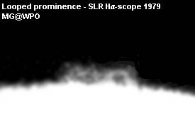
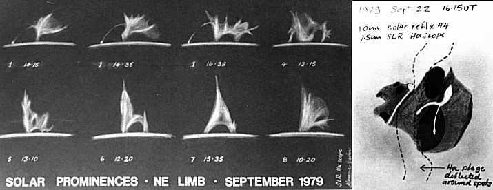
First Ha light: After many setbacks including poor weather, the first tentative views of the elusive limb prominences, filaments and plages on the disk were elating - all the more satisfying in that the unorthodox optics proved successful. It was difficult to reconcile these images as common to the same object which was producing such bland white light when viewed through an adjacent filtered reflector. Subsequently numerous sketches, particularly of prominences6, were made with this prototype instrument.
Conclusions: The experiments described are well within the capabilities of the amateur spectroscopist and consideration should be given to an all-reflecting version for stellar work, using a single mirror (Newtonian) for all imaging. The spectrohelioscope could prove its versatility over the increasingly popular monochromatic filter by using a series of reflective slits at the spectrographic focal plane to enable simultaneous scanning of various wavelengths. The reflective slit may even prove useful as a line source in optical testing - if it is not already doing so.
Acknowledgements: Grateful acknowledgement of constructive advice is extended to Professor C. P. Wynne (Royal Greenwich Observatory), W. G. Waddington (Oxford) and B. Manning (Kidderminster) in the preparation of this project.
References
1 Schroeder, D. J; Sky & Telesc.,
53, 98 (1974).
2 Cutler, H. N; Amateur Telescope
Making 1, 246, New York, 1933.
3 Bingham,R.C; private communication,
June 1979.
4 Hale, G. E; Amateur Telescope
Making, 1, 199 New York, 1933.
5 Sellars, F. J; Mem. Brit. astron.
Assoc., 37 (2), 23 (1951).
6 Gavin, M. V; The
Astronomer 16, 157 (1979).
7 Thackeray A. D; Astronomical Spectroscopy,
33, London, 1961.
8 Manning, B.W; private communication,
November 1978.
9 Moore, C. E; Solar Spectrum, NBS
Monograph, 61, 218 (1966).
10 Fitton, L. E; J. Brit. astron. Assoc.,
89 (5), 465 (1979).
Maurice Gavin - Worcester Park - Surrey - UK - 2000