|
|
|
THE COLLIMATION
|
|
|
Computer generated images, drawings and texts are property of the author and may not be reproduced or used without consent
What is collimation ?
Collimation is the adustment of the alignement of each optical element of a telescope with regard to the others. Optical books present us, for every type of telescope, design principles and theoretical performances, which implicitly suppose that this alignment is perfectly realized. Moreover, even if these books do not talk much about the damages caused by an misalignment, one must know that the performance of a reflector collapses if its optics are misaligned. In addition, no telescope, even if it has been adjusted in the factory, keeps its alignement a very long time...
The collimation is a way of improving the performance of a telescope considerably. Often, the instrument is metamorphosed. No acceptable result can be achieved at high resolution without an irreproachable collimation; image processing is incapable of compensating for the damages caused by a misalignment. Collimation is not a superfluous technique destined for opticians and purists. It is as important as the tuning of a musical instrument: the images given by a misaligned telescope can be as awful as the sound given by a out-of-tune piano. It is in the best interest of an amateur who would not want to collimate his reflector to turn to a refractor of moderate size.
Collimation is the stumbling block of reflectors; it is certainly the main cause of the mediocre reputation of SCTs. These telescopes are extremely sensitive to misalignment; their collimation can be destroyed by a fraction of turn of a collimation screw. It is one of the reasons why small refractors, seeming to defy all the diffraction laws, give better planetary images than larger reflectors with good optics (see What are the effects of obstruction ?). The benefits of good optics vanish at the smallest misalignment.
What is the precision of the proposed method ?
Because of a lack of information, few reflectors users dare to align their optics. Aditionally, the ones who venture to do it generally stop at the centering of the shadow of the secondary mirror on a much defocused star. This step is indeed necessary, on a very misaligned reflector, but it is not sufficient because of its inaccuracies. After this step, planetary images can still lose more than 50 % of their contrast.
The method presented below is the most precise; it allows reducing the final misalignment of the telescope to a practically negligible amount. It consists of observing, at high magnification, a defocused and focused star to detect any asymmetry in the diffraction patterns, a sign of a more or less pronounced misalignment. This technique needs no specialized device, just a good eyepiece and eventually a good Barlow lens. The observation of a star at high magnification is also the best way of knowing if all the conditions are favourable for high resolution observation or imaging, because it allows to check if the instrument is fully operational (thermal equilibrium, no vibration etc.) and to estimate the level of atmospheric turbulence in a more precise way than the observation of a planet.
When checking a reflector ?
People who think that a SCT does not need to be collimated very often probably do not realize the level of precision required for this type of instrument. The constraints are so high that a simple car trip always changes the alignment in small amounts, and sometimes in large amounts. Collimation can even vary according to the orientation of the optical tube (with a German mount, an interesting experiment is to point at the same star at the meridian successively from the left and the right of the mount, to observe the modification of collimation due to the reversal of the tube). This is the reason why it is advised to choose a star in the same area as the object of interest (planet or Moon). If a small misalignment can be tolerated in deep-sky observation, it is taking a big risk not checking the collimation before a planetary session. The idea is that the alignment becomes as familiar as checking the oil level or the pressure of the tires in a car before a trip !
Is the collimation difficult or risky ?
On SCTs, the only accessible alignment is the one of the secondary mirror. Three screws (push or pull), or three couples of screws (push-pull) on certain telescopes, allow to modify the orientation of this mirror. The process of collimation is iterative (check-align-check-align etc.) and is neither difficult nor risky, if some simple precautions are followed:
- the central screw, which holds the secondary mirror, must never be touched,
- the three screws must be screwed or unscrewed in moderation, no screw being overtightened or totally unscrewed,
- when a screw is unscrewed, the two others must be screwed.
- the rotations made on the screws must be small: a very misaligned mirror can need 1/2 turn, but the final alignment is made by fractions of a turn, nearly by a flexure of the tool.
- each time an adjustment is made on the screws, the star, which has moved in the field because of the adjustment, must be precisely recentered.
On a Newtonian telescope, the collimation is usually made in two steps: geometric alignement of the secondary mirror (with the help of a collimation eyepiece), and then precise alignment of the primary mirror. The method presented below corresponds to this second step.
The collimation must be made only when the instrument is in thermal equilibrium. If it is not the case, air veins inside the tube of the telescope distort diffraction patterns and can make the alignment difficult or even erroneous.
A star diagonal can be used, on the condition that it does not introduce optical aberrations. Such an accessory usually shifts the image given by the instrument: the center of the field is not the same with and without it. If the purpose of the night is visual observation, it is better to collimate with the star diagonal. In this case, the star will be precisely centered in the field of the eyepiece. On the other hand, if photography or CCD imaging is planned, it is better to put the star at a place corresponding to the center of the film or the CCD chip, even if it appears not centered in the star diagonal. Furthermore, when a star diagonal is used, the up-down reversal of the image that it introduces must be taken into account to determine the connection between the asymmetry of the diffraction pattern and the screw to be touched.
The figures presented below have been made by computer and are very typical of what can be seen in a Schmidt-Cassegrain, a classical or Dall-Kirkham Cassegrain, or a Newtonian (dominant coma). In other types of instruments (refractor, Ritchey-Chrétien Cassegrain), the diffraction images given by a misaligned telescope can differ (astigmatism can be mixed with coma, or even dominate it). Nevertheless, whatever the instrument, a good alignment always materializes by a perfectly symmetrical diffraction pattern.
How to collimate the reflector
First step
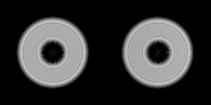
The first step consists in observing a bright star (magnitude 0 or 1) at a magnification of about the diameter of the telescope in millimeters (ex.: 200x for a 200 mm). When the star is strongly defocused (figures below), it appears as a donut, the central hole being the shadow of the secondary mirror. This shadow must be perfectly centred (left figure). If it is shifted (right figure), it is necessary to have an effect on the collimation screw(s) situated in the direction of the shift (it may be useful to think with clock hours). If a star diagonal is in place, do not forget to take the up-down reversal of the image into account. if your arm is long enough, you can also put a finger in front of the aperture of the telescope and see the position where it corresponds to the shift.
Only a very misaligned telescope (like can be a telescope which is never collimated) needs this rough alignment. If collimation is regularly checked, no asymmetry usually appears at this step.
Second step
The second step needs a dimmer star (magnitude 2 to 3) high above the horizon to minimize the effects of the atmospheric turbulence, and a higher magnification: 2 to 3 times the diameter of the telescope in mm (ex.: 500x for 200 mm). Do not hesitate to enlarge the image as much as possible, collimation defects are better visible. The star is slightly defocused back and forth (intra-focal and extra-focal patterns). A complex system of rings and central bright point appear (figures below).This system must open and close itself in a perfectly concentric and symmetrical manner and the bright point must be at the center of the rings (upper series). If it is not the case (lower series), the screws situated on the side of the asymmetry must be touched, like at the first step.
|
intra-focal |
focus |
extra-focal |
|
|
||
It must be noticed that the misalignment presented above would not have been visible at the first step.
Third step
Final alignment is made in the same conditions as the previous step, but this time the star is carefully focused. The famous Airy pattern appears: a false disk surrounded by diffraction rings of decreasing brightness (figures below). If collimation is good (figure A), the first diffraction ring around the disk is complete and uniform. If this ring is not uniform (figure B), or if it is incomplete (figures C and D), one must adjust very slightly the collimation screws as in the previous steps.
|
|
|
|
|
From one figure to the next, the angle of misalignment of the mirror has been doubled. The worst misalignment (fig. D) represents only a fraction of turn of a collimation screw of a SCT. On this type of instrument, the transition from fig. A to fig. B represents less than 1/20th of a turn, a modification of the orientation of the optical tube can be sufficient to produce this effect. It is evident that the precision of alignment increases with each step.
Unlike the previous steps which can tolerate a mediocre seeing, this last step needs good conditions of turbulence. Anyway, if no Airy pattern can be discerned, no high resolution result can be expected (except in big telescopes for whom the Airy pattern is rarely or even never visible).
A good way of familiarizing oneself with Airy patterns is to strongly diaphragm the telescope (at 50 mm for example) and to observe a star at a magnification of 100 to 150x. However, it is out of question to collimate the telescope with the diaphragm in place !
What are the effects of misalignment on contrast and resolution ?
Each figure below (see What is a MTF curve ?) shows the MTF curves corresponding to each of the three misalignments presented above (fig B, C and D), in comparison with the theoretical curve of a 20 % obstructed telescope perfectly collimated. The added curves correspond to a spherical aberration and an increased obstruction. All curves have been adjusted to coincide, to compare the damages due to misalignment to other causes of performance deterioration.
|
|
|
|
A 20 % obstructed telescope misaligned at this level has the same efficiency as if it was affected by : - a spherical aberration of l/2 on the wave - an obstruction of 69 % At low frequencies, the instrument loses 2/3 of its capacities (effective diameter 85 mm for a 250 mm telescope). |
|
|
|
|
|
A 20 % obstructed telescope misaligned at this level has the same efficiency as if it was affected by : - a spherical aberration of l/3,5 on the wave - an obstruction of 43 % At low frequencies, the instrument loses 1/3 of its capacities (effective diameter 157 mm for a 250 mm telescope). |
|
|
|
|
|
A 20 % obstructed telescope misaligned at this level has the same efficiency as if it was affected by : - a spherical aberration of l/7 on the wave - an obstruction of 27 % At low frequencies, the instrument loses 1/8 of its capacities (effective diameter 220 mm for a 250 mm telescope). |
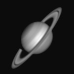
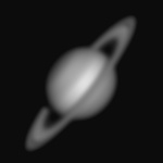
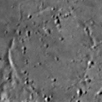
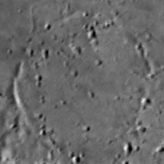
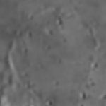
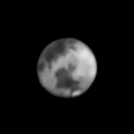
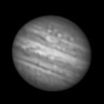
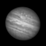
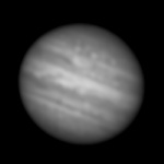
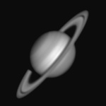
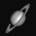
What are the effects of misalignment on planetary images ?
MTF curves allow simulating the effects of misalignment on real images. Below each Airy pattern corresponding to a given misalignment, is placed the image that the instrument would have given if it were affected by such a defect.
|
|
|
|
|
|
|
|
|
|
|
|
|
|
|
|
|
|
|
|
|
|
|
|
|
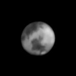
The first level of misalignment (second column) has small effects, it can be considered as the limit of acceptable misalignement for high resolution. Nevertheless, it already corresponds to a spherical aberration of l/7 on the wave, and it will pile up with other problems and aberrations. So, since a simple fraction of a turn on a collimation screw can suppress it, why go without this easy gain ? There are so many more complex problems to solve !
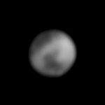
The second level of misalignment (third column) has stronger effects; the damages are unacceptable in high resolution.
The third level (last column) lead to a crushing of the performances of the telescope, far ahead the effects of the highest existing obstruction. The instrument loses about the 2/3 of its capacities. At this level, good optics look like lemons, the lambdas so dearly payed melt away. Unfortunately, the experience shows that most of the working reflectors suffer from misalignment equal or worse than this one. With good reason, nobody would put up with a telescope obstructed at 60 % or more, but a majority of users implicitly accept to suffer from worse damages due to misalignment. However, the major difference between obstruction and misalignment is that we can do nothing against the first and we can do everything against the second !